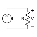
مصدر تيار
| تحليل خطي للشبكات | |
|---|---|
| العناصر | |
| المكونات | |
| دوائر التوالي والتوازي | |
| تحويلات المعاوقة | |
| مبرهنات المولد | مبرهنات الشبكة |
| أساليب تحليل الشبكات | |
| Two-port parameters | |
مصدر التيار، هو جهاز إلكتروني أو كهربائي يقوم بتوصل التيار الكهربائي.
. . . . . . . . . . . . . . . . . . . . . . . . . . . . . . . . . . . . . . . . . . . . . . . . . . . . . . . . . . . . . . . . . . . . . . . . . . . . . . . . . . . . . . . . . . . . . . . . . . . . . . . . . . . . . . . . . . . . . . . . . . . . . . . . . . . . . . . . . . . . . . . . . . . . . . . . . . . . . . . . . . . . . . . .
مصادر الكهرباء القياسية
| Voltage source | Current Source |
| Controlled Voltage Source | Controlled Current Source |
| Battery of cells | Single cell |
مصادر التيار الفيزيائية
Resistor current source
Active current sources
JFET and N-FET current source
Simple transistor current source
Voltage across R2 (VR2) is given by VZ - VBE, where VBE is the base-emitter drop of Q1.
or , since VBE is typically 0.65 V for a silicon device.[1]
Simple transistor current source with diode compensation
Resistance R2 is now calculated as
Since VD = VBE = 0.65 V,[2]
Therefore,
(In practice VD is never exactly equal to VBE and hence it only suppresses the change in VBE rather than nulling it out.)
and R1 is calculated as
(the compensating diode's forward voltage drop VD appears in the equation and is typically 0.65 V for silicon devices.[3])
Simple transistor current source with LED
and R1 as
, where ID is the LED current.
التغذية
تيار منعكس
مصادر عملي أخرى
Inductor type current source
مصادر التيار عالي الجهد
مقارنة مصادر الجهد والتيار
. . . . . . . . . . . . . . . . . . . . . . . . . . . . . . . . . . . . . . . . . . . . . . . . . . . . . . . . . . . . . . . . . . . . . . . . . . . . . . . . . . . . . . . . . . . . . . . . . . . . . . . . . . . . . . . . . . . . . . . . . . . . . . . . . . . . . . . . . . . . . . . . . . . . . . . . . . . . . . . . . . . . . . . .
انظر أيضا
- Voltage-to-current converter
- تيار منعكس
- Iron-hydrogen resistor
- Widlar current source
- Wilson current source
- Current loop
- Welding power supply, a device used for arc welding, many of which are designed as constant current devices.
- Current sources and sinks
المصادر والهوامش
- ^ The value for VBE varies logarithmically with current level: for more detail see diode modelling.
- ^ See above note on logarithmic current dependence.
- ^ See above note on logarithmic current dependence.
قراءات اضافية
- "Current Sources & Voltage References" Linden T. Harrison; Publ. Elsevier-Newnes 2005; 608-pages; ISBN 0-7506-7752-X
